Wednesday, May 13, 2009

The Worlds 10 Longest Bridge

Do you know the top 10 Longest Bridge in the World?

Well lets find out….

1. Lake Pontchartrain Causeway

Ten Longest Bridges In the World

The Lake Pontchartrain Causeway, or the Causeway, consists of two parallel bridges that are the longest bridges in the world by total length.[2] These parallel bridges cross Lake Pontchartrain in southern Louisiana. The longer of the two bridges is 23.87 miles (38.42 km) long. The bridges are supported by over 9,000 concrete pilings. The two bridges feature bascule spans over the navigation channel 8 miles (13 km) south of the north shore. The southern terminus of the Causeway is in Metairie , Louisiana , a suburb of New Orleans . The northern terminus is at Mandeville , Louisiana .
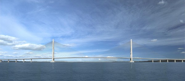
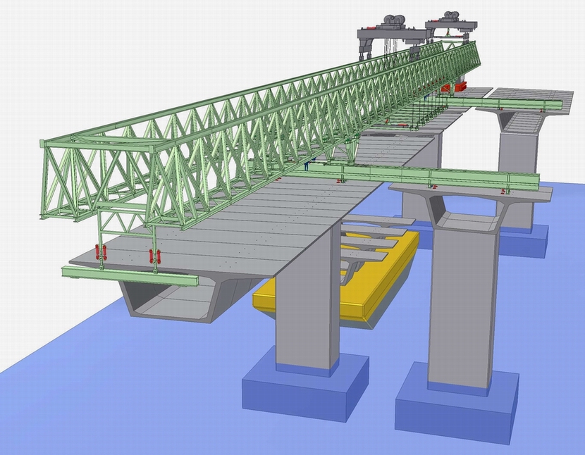
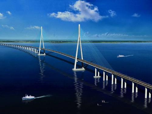
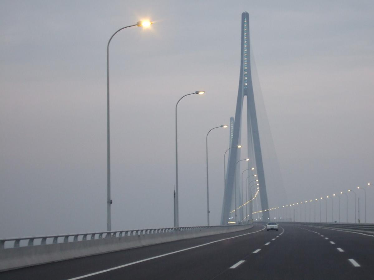
2. Donghai Bridge

Ten Longest Bridges In the World

Donghai Bridge (literally “ East Sea Grand Bridge ”) is the longest cross-sea bridge in the world and the longest bridge in Asia . It was completed on December 10, 2005. It has a total length of 32.5 kilometres (20.2 miles) and connects Shanghai and the offshore Yangshan deep-water port in China . Most of the bridge is a low-level viaduct. There are also cable-stayed sections to allow for the passage of large ships, largest with span of 420 m.

3. King Fahd Causeway

The King Fahd Causeway is multiple dike - bridge combination connecting Khobar , Saudi Arabia , and the island nation of Bahrain .

Ten Longest Bridges In the World

A construction agreement signed on July 8, 1981 led to construction beginning the next year. The cornerstone was laid on November 11, 1982 by King Fahd of Saudi Arabia and Sheikh Isa bin Salman al-Khalifa of Bahrain ; construction continued until 1986, when the combination of several bridges and dams were completed. The causeway officially opened for use on November 25, 1986.

4. Chesapeake Bay Bridge

http://imagecache.allposters.com/images/pic/147/BB%7EChesapeake-Bay-Bridge-Posters.jpg

The Chesapeake Bay Bridge (commonly known as the Bay Bridge ) is a major dual-span bridge in the U.S. state of Maryland ; spanning the Chesapeake Bay, it connects the state’s Eastern and Western Shore regions. At 4.3 miles (7 km) in length, the original span was the world’s longest continuous over-water steel structure when it opened in 1952. The bridge is officially named the William Preston Lane , Jr. Memorial Bridge after William Preston Lane, Jr. who, as governor of Maryland , implemented its construction.

5. Vasco da Gama Bridge

Ten Longest Bridges In the World

The Vasco da Gama Bridge (Portuguese: Ponte Vasco da Gama, pron. IPA: [’põt(?) ‘va?ku d? ‘g?m?]) is a cable-stayed bridge flanked by viaducts and roads that spans the Tagus River near Lisbon , capital of Portugal . It is the longest bridge in Europe (including viaducts), with a total length of 17.2 km (10.7 mi), including 0.829 km (0.5 mi) for the main bridge, 11.5 km (7.1 mi) in viaducts, and 4.8 km (3.0 mi) in dedicated access roads. Its purpose is to alleviate the congestion on Lisbon ’s other bridge (25 de Abril Bridge ), and to join previously unconnected motorways radiating from Lisbon .

6. Penang Bridge

Ten Longest Bridges In the World

The Penang Bridge (Jambatan Pulau Pinang in Malay) E 36 is a dual-carriageway toll bridge that connects Gelugor on the island of Penang and Seberang Prai on the mainland of Malaysia on the Malay Peninsula . The bridge is also linked to the North-South Expressway in Prai and Jelutong Expressway in Penang . It was officially opened to traffic on September 14, 1985. The total length of the bridge is 13.5 km (8.4 miles), making it among the longest bridges in the world, the longest bridge in the country as well as a national landmark. PLUS Expressway Berhad is the concession holder which manages it.

7. Rio-Niteroi Bridge

Ten Longest Bridges In the World

The Rio-Niteroi Bridge is a reinforced concrete structure that connects the cities of Rio de Janeiro and Niteroi in Brazil .
Construction began symbolically on August 23, 1968, in the presence of Queen Elizabeth II of the United Kingdom and Prince Philip, Duke of Edinburgh, in their first and thus far only visit to Brazil. Actual work begun in January, 1969, and it opened on March 4, 1974.
Its official name is “President Costa e Silva Bridge ”, in honor of the Brazilian president who ordered its construction. “Rio-Niteroi” started as a descriptive nickname that soon became better known than the official name. Today, hardly anyone refers to it by its official name.

8. Confederation Bridge

Ten Longest Bridges In the World

The Confederation Bridge (French: Pont de la Confédération) is a bridge spanning the Abegweit Passage of Northumberland Strait, linking Prince Edward Island with mainland New Brunswick, Canada. It was commonly referred to as the “Fixed Link” by residents of Prince Edward Island prior to its official naming. Construction took place from the fall of 1993 to the spring of 1997, costing $1.3 billion. The 12.9-kilometre (8 mi) long bridge opened on 31 May 1997.

9. San Mateo-Hayward Bridge

Ten Longest Bridges In the World

The San Mateo-Hayward Bridge (commonly called San Mateo Bridge ) is a bridge crossing California ’s San Francisco Bay in the United States , linking the San Francisco Peninsula with the East Bay . More specifically, the bridge’s western end is in Foster City , the most recent urban addition to the eastern edge of San Mateo . The eastern end of the bridge is in Hayward . The bridge is owned by the state of California , and is maintained by Caltrans, the state highway agency..

10. Seven Mile Bridge

Ten Longest Bridges In the World

The Seven Mile Bridge , in the Florida Keys, runs over a channel between the Gulf of Mexico and the Florida Strait, connecting Key Vaca (the location of the city of Marathon , Florida ) in the Middle Keys to Little Duck Key in the Lower Keys. Among the longest bridges in existence when it was built, it is one of the many bridges on US 1 in the Keys, where the road is called the Overseas Highway .

Tuesday, May 12, 2009

Dubai Metro Extension

Dubai Metro's Green Line extension study is in the design stage and will be completed in 60 months, according to a senior official at RTA.
"The Green Line extension study is in the design stage and was awarded in March to consultant Systra-Parson International," said Abdul Redha Abu Al Hassan, Director of Planning and Development, Rail Agency, RTA, in an exclusive to Emirates Business. "The project timeline is 60 months and it includes design, feasibility studies and preparation of tender documents."
He was speaking on the sidelines of the Mena rail 2009 organised by Terrapin.
The Green Line extension goes from Jed Hafs Station 2 through the Lagoons project and will then connect to the Emirates Road. "If we have the Blue Line in future, then it will also connect to that line," said Al Hassan.
The RTA's yearly budget is Dh12 billion to Dh15bn, he said. "It will be reduced over the years as most of the infrastructure work will be completed," he said.
RTA has plans to have up to 320km of rail by 2020.
Meanwhile, the RTA also started a new study called Integrated Rail Master Plan in February, Al Hassan said.
"It is a revision of the rail line footprint. It will look at the rail lines in Dubai and based on the current information and the growth of the emirate, we will revisit all the lines again and look at the conceptual layout and how to integrate all the lines," he said. "We will try to put new programmes for the new lines and the phases of the various projects."
The study has been assigned to Parsons Brinckerhoff and will be ready by 2010. "It is a revision of the line footprint. At the end of the study, RTA will revise its master plan," said Al Hassan.
Al Hassan said the Purple Line is on hold and RTA is waiting for developers to get back in order to make the project feasible.
"We were ready to go for tender but it has stopped due to the recession and the fact that many developers have stopped their projects. We do not want to do a project that is serving no one," he said. "It will take time to start again after we get new information from the developers who are rescheduling and replanning their projects."
Meanwhile, the Sufouh tram system has delayed its Phase 2 works due to major ongoing road works on one hand and the 'on hold' status of the Sama Dubai project (Jumeirah Hills) on the other.
"Phase 1 is not a problem but we are waiting for the project to materialise and then can go ahead with Phase 2," said Al Hassan. "The constructions of the stations in Phase 1 will commence by December and the project will be completed by April 2011."
The 9km Phase 1 will consist of 13 stations and will service Dubai Marina, both Media and Internet cities and the Al Sufouh area.
The first phase's lines are being built by the ABS consortium comprising Alstom, Besix and Serco.
The second phase is intended to service Burj Al Arab and Jumeirah Beach Hotel and will stretch 5km with six stations. The tram will link up with the Red Line of the Dubai Metro at three points on Sheikh Zayed Road, and with the monorail on The Palm Jumeirah where it meets Al Sufouh Road.
Al Hassan admitted that if certain projects are not ready, then some of the stations on the Red Line will not be operational.
"If developers will continue with their projects, then the stations will be operational," he said. "Otherwise the trains will go through the stations, which will be fully constructed."
The Red Line has finished 100 per cent of the construction of its viaduct (52km) and 10km of tunnel construction. Construction on all underground and above ground stations has almost been completed, he said.
The Green Line expects to finish 100 per cent of the viaduct this month and 100 per cent of tunnel construction. "All stations are expected to be finished by December and will be operational by March 2010," he said.

Monday, May 11, 2009

Earthquake could destroy 520 bridge, too, study says

An Article By LARRY LANGE

So you thought the Alaskan Way Viaduct was on shaky ground? Now you can worry about the state Route 520 bridge, too.

A recent engineering analysis, quietly discussed among state transportation officials and planners, says a magnitude-6.5 earthquake in the wrong spot could take out both structures.

The analysis says the viaduct fronting Elliott Bay and the bridge crossing Lake Washington have about the same ability to withstand the kind of major earthquake that occurs on average every 210 years. It is widely accepted that this region is at risk of catastrophic quakes.

To put it bluntly, a quake ranging in magnitude from 6.5 to 7.2, located close to the Earth's surface and near the spans, could destroy either structure or both.

The odds of this actually occurring have not been determined, state bridge engineer Patrick Clarke said.

Last year's major earthquake, centered near Olympia, registered a magnitude 6.8 but was centered 35 miles underground and 60 miles to the south -- too far away to destroy either span. Still, it was forceful enough to damage both, and to close the viaduct for several days for inspections and repairs.

Losing the bridge and viaduct, besides being deadly, could cripple traffic for years.

More than 225,000 drivers now use the two bridges every day, and would be forced to use side streets or other already-strained highways.

Rush-hour traffic backups could routinely extend south on Interstate 5 as far as the Boeing Access Road or east on Interstate 90 as far as Interstate 405, said Morgan Balogh, the state's regional traffic operations engineer.

"It gets ugly in a hurry, I'm sure," said Les Rubstello, manager of the state's Trans-Lake Washington study examining ways to improve mobility in the 520 corridor.

Replacing the 520 bridge could cost from $1.8 billion for four lanes to $7.4 billion for eight lanes, according to recent state estimates. Construction, depending on the option chosen, could last from nine to 11 years.

That the 520 bridge is as quake-vulnerable as the viaduct was startling news to some.

It was "new information for me," said King County Councilman Dwight Pelz, chairman of the council's Transportation Committee and a key player in planning a regional ballot measure to pay for major highway and transit improvements.

The quake analysis actually has been around for several months and was known to state officials and to some members of an advisory committee discussing whether to rebuild or replace 520's Evergreen Point Bridge.

Rubstello said the state didn't formally release details to avoid sounding "like we were crying wolf twice" after much-publicized reports about the viaduct's vulnerability to tremors.

In February, state Transportation Secretary Doug MacDonald urged legislators and Gov. Gary Locke to set aside money to plan replacements for both the viaduct and 520 bridge.

The letter did not mention the earthquake risk but said the 520 bridge is vulnerable to high winds and waves, which could break it apart.

"I've been flapping my lips at every meeting that it's an unsafe facility," said Redmond Mayor Rosemarie Ives. "Nobody wants to listen."

The quake analysis "serves to move 520 (replacement) up on the regional priority list," Pelz said.

Doing this, however, could reignite controversies about the effects of a bigger new bridge on the shorelines it connects. And some, including transit advocate Peter Hurley, want to see more detailed information before they agree that replacing the bridge makes more financial sense than retrofitting it to better resist earthquakes.

Engineers have long said that a major quake could fatally damage the viaduct, a 2.2-mile, double-deck structure that carries state Route 99 along the Seattle waterfront from the port docks to Aurora Avenue.

They have said the viaduct, which carries about 110,000 vehicles on an average weekday, could collapse if ground gives way under part of it, or if concrete cracks and support columns shear.

In a report issued a year ago, a team of engineers recommended replacing the viaduct, saying retrofitting it to meet modern earthquake standards didn't make sense.

That report came four months after an earthquake did more than $1.7 million in damage to the viaduct, cracking it and prompting crews to close parts of it for several days while it was shored up.

The same Feb. 28, 2001, earthquake that opened cracks in the viaduct did minor damage to the 520 bridge, loosening bolts in a joint on the western approach span.

Ilustration

A 1993 earthquake-evaluation study concluded that the tops of the 520 bridge's approach supports near each shoreline, filled with concrete five feet down from the top, would bend enough in an earthquake to hold up.

But that's no longer accepted. Below those solid "caps," the supports are hollow shells with 5-inch outer walls. State officials said researchers in California later became skeptical about how well hollow columns would hold up.

After a tug and barge hit and shattered one of the 520 bridge columns two years ago, Washington state engineers re-evaluated the earlier conclusion.

And in a memo three months ago, two state engineers said the caps wouldn't bend enough in an earthquake to keep the bridge supported.

That conclusion also was included in a brief internal state Transportation Department report in January. This said that even though the double-deck viaduct and the floating 520 bridge are built differently, the earthquake risks to the two structures when faced with the 210-year earthquake "are almost identical."

Rubstello said state analysts are just beginning to calculate how motorists would react to the simultaneous loss of both structures. Balogh, the state engineer, said backups would be longer on I-5 and I-90 and congestion would worsen on other highways as drivers tried to compensate for the loss of the two spans.

"You're not going to sit on the freeway for an hour. You're going to risk it on an arterial" (street), he said.

Some think the earthquake risk makes the 520 bridge a higher replacement priority. State officials have said retrofitting the 520 bridge for safety is not worthwhile because of its age, though they did do $1.14 million in retrofitting work in 1999.

Even people in Seattle's Montlake neighborhood, where the bridge's west approach is located, agree it should be replaced, said Jonathan Dubman, president of Montlake Community Club.

But the question is: With what? The advisory committee hasn't decided how many lanes a new span should have. That's a big issue in Dubman's neighborhood where, depending on the width of a new bridge, people living 200 feet from it now "could be as close as 20 feet to the new highway."

"The neighborhood would support an effective transportation solution that would improve the quality of life along the (520) corridor and through the region," Dubman said. "But we have some work to do to figure out a solution."

Saturday, May 9, 2009

Dubai's Mile-Long Super Arch Bridge

Dubai is going ahead with another ambitious project which is a super arch bridge. Dubai's next super structure will stand higher than the George Washington Bridge (604 ft.) but fall short of San Francisco's existing Golden Gate Bridge (746 ft.).

Thursday, May 7, 2009

I-35W Bridge Collapse

A lesson which had made our bridge engineering safer.

I-35W Bridge History

  • Built in 1964 by Hurcon Inc. and Industrial Construction Company.
  • Steel trusses and deck were constructed by Industrial Construction Company in the summer of 1965.
  • Bridge opened to traffic in 1967.
  • Scheduled for reconstruction in 2020-25.

Stats

  • Bridge carries 144,000 vehicles per day; including 4,760 commercial vehicles.
  • Similar bridges in Minnesota include the Hwy. 123 bridge in Sandstone and the Hwy. 23 bridge over the Mississippi River in St. Cloud.

Design

  • Deck steel truss is made up of three parts: deck, superstructure and substructure (the structure under water).
  • Bridge has a split deck (longitudinally parallel to traffic) and is 113 feet, 4 inches wide.
  • Size/length: 1,907 feet long, eight lanes.

Inspection History

  • Had been inspected annually since 1993; before that, was inspected every two years
  • Last fully inspected in 2006. Partial inspections were conducted in 2007; to be complete in fall 2007 (see inspection reports on I-35W bridge online at www.mndot.gov -- scroll to bottom of page to find documents)
  • The 2006 Fracture Critical Bridge Inspection Report, prepared by a MnDOT bridge inspection team, describes specific problems that caused the superstructure (part of bridge above water) to receive a poor rating. The poor rating can be attributed to corrosion at some areas where the paint system has deteriorated, poor weld details in the steel truss members and floor beams, bearings that are not moving as they were designed to move, and existing fatigue crack repairs to the truss cross beam and approach spans.
  • Deficiencies were acknowledged in the 2005, 2006 and 2007 inspection reports.
  • MnDOT had taken several steps to address these deficiencies. Some cracking in the approach spans was repaired or was being monitored. The Bridge Office had contracted with the University of Minnesota in 1990 to evaluate the fatigue stresses within the truss. Field tests were conducted. Measured and calculated stress ranges were less than the fatigue threshold, therefore, it was concluded that fatigue cracking was not expected in the deck truss. The following actions were recommended:
  • Structural components of the main truss with the highest stress ranges should be inspected thoroughly, every two years.
  • Critical locations of the floor trusses had high stress ranges, and should be inspected every six months.
  • Although the report concluded that fatigue cracking was not expected to be a problem for the weld details used on the truss, MnDOT contracted with URS (a private firm) in 2003 to do a more in-depth fatigue and fracture analysis, and to determine whether the fracture of any single truss member would result in collapse of the bridge or whether the traffic load would be safely carried by other members of the bridge. URS made three recommendations in January 2007:

1) Add redundant plating over the most critical 52 truss members,

2) Conduct a visual examination of all suspected weld details and remove measurable defects at suspected weld details of all 52 fracture critical truss members, or,

3) Do a combination of both 1) and 2).

MnDOT had begun inspection of the weld details and no weld cracks were detected. Therefore, MnDOT did not proceed with option 1 at that time. MnDOT intended to complete the inspection of the weld details on all of the remaining members after the completion of the current construction project.

Structurally deficient bridges

  • A bridge is rated as “structurally deficient” when part of the bridge is found to be in poor condition. Many bridges in poor condition are still safe for use. As deterioration continues, engineering analysis is sometimes necessary to re-compute the safe load capacity of the bridge. If the safe load capacity is less than today’s legal truck load (80,000 pounds), the bridge is posted at the newly computed safe load capacity.
  • The I-35W bridge was rated safe for legal truck loads and permitted overweight truck loads of up to 136,000 lbs. The bridge was not under any restrictions.

· The condition of different parts of a bridge is rated on a scale of 1 to 9 (7, 8, or 9 are good condition ratings, 6 is satisfactory, 5 is fair, 4 is poor, 3 is serious, 2 is critical and 1 is closed). A structurally deficient bridge is one for which the deck, the superstructure or the substructures are rated in condition 4 or less. For this bridge, the superstructure was rated 4.

  • In Minnesota, there are 1,097 bridges that are considered structurally deficient and that have a sufficiency rating less than or equal to 80. Of these bridges, 106 are on the state trunk highway system and 991 are on the local system.

Federal report on bridges (NBIS database)

  • The National Bridge Inspection Standards require states to annually report condition ratings for all bridges in their states to the Federal Highway Administration (FHWA). Each MnDOT district has inspectors who are trained to inspect and rate bridge condition. That information is forwarded to MnDOT’s Bridge Office where it is compiled and forwarded to the FHWA. The FHWA uses that data to determine which bridges are structurally deficient and functionally obsolete.

Recent work on the bridge

  • Work involved concrete and joint repair, lighting and guardrail installation
  • Work was scheduled to be complete Sept. 30.
  • Cost for the work is $9 million.

Wednesday, May 6, 2009

Tacoma Bridge Disaster

http://www.youtube.com/watch?v=HxTZ446tbzE

The Tacoma Bridge Engineering Disaster has been a turning point which had saved a lot of lives and making bridge engineering a lot safer.

The original Tacoma Narrows Bridge was opened to traffic on July 1, 1940. It was located in Washington State, near Puget Sound.
The Tacoma Narrows Bridge was the third-longest suspension bridge in the United States at the time, with a length of 5939 feet including approaches. Its two supporting towers were 425 feet high. The towers were 2800 feet apart.
Design
Prior to this time, most bridge designs were based on trusses, arches, and cantilevers to support heavy freight trains. Automobiles were obviously much lighter. Suspension bridges were both more elegant and economical than railway bridges. Thus the suspension design became favored for automobile traffic. Unfortunately, engineers did not fully understand the forces acting upon bridges. Neither did they understand the response of the suspension bridge design to these poorly understood forces.
Furthermore, the Tacoma Narrows Bridge was built with shallow plate girders instead of the deep stiffening trusses of railway bridges. Note that the wind can pass through trusses. Plate girders, on the other hand, present an obstacle to the wind.
As a result of its design, the Tacoma Narrows Bridge experienced rolling undulations which were driven by the wind. It thus acquired the nickname "Galloping Gertie."
Failure
Strong winds caused the bridge to collapse on November 7, 1940. Initially, 35 mile per hour winds excited the bridge's transverse vibration mode, with an amplitude of 1.5 feet. This motion lasted 3 hours.
The wind then increased to 42 miles per hour. In addition, a support cable at mid-span snapped, resulting in an unbalanced loading condition. The bridge response thus changed to a 0.2 Hz torsional vibration mode, with an amplitude up to 28 feet. The torsional mode is shown in Figures 1a and 1b.
Figure 1a. Torsional Mode of the Tacoma Narrows Bridge
Figure 1b. Torsional Mode of the Tacoma Narrows Bridge
The torsional mode shape was such that the bridge was effectively divided into two halves. The two halves vibrated out-of-phase with one another. In other words, one half rotated clockwise, while the other rotated counter-clockwise. The two half spans then alternate polarities.
One explanation of this is the "law of minimum energy." A suspension bridge may either twist as a whole or divide into half spans with opposite rotations. Nature prefers the two half-span option since this requires less wind energy.
The dividing line between the two half spans is called the "nodal line." Ideally, no rotation occurs along this line.
The bridge collapsed during the excitation of this torsional mode. Specifically, a 600 foot length of the center span broke loose from the suspenders and fell a distance of 190 feet into the cold waters below. The failure is shown in Figures 2a and 2b.
Figure 2a. Failure of the Tacoma Narrows Bridge
Figure 2b. Tacoma Narrows Bridge after the Failure
Failure Theories
Candidates
The fundamental weakness of the Tacoma Narrows Bridge was its extreme flexibility, both vertically and in torsion. This weakness was due to the shallowness of the stiffening girders and the narrowness of the roadway, relative to its span length.
Engineers still debate the exact cause of its collapse, however. Three theories are:
1. Random turbulence
2. Periodic vortex shedding
3. Aerodynamic instability (negative damping)
These theories are taken from Reference 1. Aerodynamic instability is the leading candidate.
Random Turbulence
An early theory was that the wind pressure simply excited the natural frequencies of the bridge. This condition is called "resonance." The problem with this theory is that resonance is a very precise phenomenon, requiring the driving force frequency to be at, or near, one of the system's natural frequencies in order to produce large oscillations. The turbulent wind pressure, however, would have varied randomly with time. Thus, turbulence would seem unlikely to have driven the observed steady oscillation of the bridge.
Vortex Shedding
Theodore von Karman, a famous aeronautical engineer, was convinced that vortex shedding drove the bridge oscillations. A diagram of vortex shedding around a spherical body is shown in Figure 3. Von Karman showed that blunt bodies such as bridge decks could also shed periodic vortices in their wakes.
A problem with this theory is that the natural vortex shedding frequency was calculated to be 1 Hz. This frequency is also called the "Strouhal frequency." The torsional mode frequency, however, was 0.2 Hz. This frequency was observed by Professor F. B. Farquharson, who witnessed the collapse of the bridge. The calculated vortex shedding frequency was five times higher than the torsional frequency. It was thus too high to have excited the torsional mode frequency.
In addition to "von Karman" vortex shedding, a flutter-like pattern of vortices may have formed at a frequency coincident with the torsional oscillation mode. Whether these flutter vortices were a cause or an effect of the twisting motion is unclear.
Figure 3. Vortex Shedding around a Spherical Body
Aerodynamic Instability
Aerodynamic instability is a self-excited vibration. In this case, the alternating force that sustains the motion is created or controlled by the motion itself. The alternating force disappears when the motion disappears. This phenomenon is also modeled as free vibration with negative damping.
Airfoil flutter and transmission line galloping are related examples of this instability. Further explanations of instability are given in References 2 , 3, and 4.
The following scenario shows how aerodynamic instability may have caused the Tacoma Narrows Bridge to fail. For simplicity, consider the motion of only one span half.
Assume that the wind direction was not perfectly horizontal, perhaps striking the bridge span from below, as shown in Figure 4a
Thus, the bridge is initially at an angle-of-attack with respect to the wind. Aerodynamic lift is generated because the pressure below the span is greater than the pressure above. This lift force effectively places a torque, or moment, on the bridge. The span then begins to twist clockwise as show in Figure 4b. Specifically, the windward edge rotates upward while the leeward edge rotates downward.

The span has rotational stiffness, however. Thus, elastic strain energy builds up as the span rotates. Eventually, the stiffness moment overcomes the moment from the lift force. The span then reverses its course, now rotating counter-clockwise
The span's angular momentum will not allow it to simply return to its initial rest position, however. The reason is that there is little or no energy dissipation mechanism. Thus, the span overshoots its initial rest position. In fact, it overshoots to the extent that the wind now strikes the span from above as shown in Figure 4c. The wind's lift force now effectively places a counter-clockwise moment on the span.
Once again, strain energy builds up in the span material. Eventually, the stiffness moment exceeds the moment from the wind's lift force. The span thus reverse course, now rotating clockwise. Again, it overshoots its rest position. The cycle of oscillation begins anew from the position shown in Figure 4a, except that the span now has rotational velocity as it passes through the original rest position.
The cycles of oscillation continue in a repetitive manner.
Note that the wind force varies as a function of the span angle during the cycle. The wind force may also vary with the angular velocity. The wind force is not a function of time, however.
Eventually, one of two failure modes occurs. One possibility is that the span experiences fatigue failure due to an excessive number of stress reversals. The other is that the angular displacement increased in an unstable manner until the material is stressed beyond its yield point, and then beyond its ultimate stress limit.
In reality, these two failure modes are interrelated. For example, accumulated fatigue effectively lowers the yield and ultimate stress limits. Regardless, the bridge collapses.
As a final note, the aerodynamic instability oscillation is not a resonant oscillation since the wind does not have a forcing frequency at, or near, the bridge's torsional mode frequency. Some physics and engineering textbooks mistakenly cite the Tacoma Narrows Bridge as an example of resonance. This problem is discussed in Reference 5.
Nevertheless, the bridge's collapse remains the most well-know structural failure due to vibration.
Replacement Bridge
A new Tacoma Narrows Bridge was built in 1950, as shown in Figure 5. The second bridge had truss-girders which allowed the winds to pass through. It also had increased torsional stiffness because it was thicker and wider. Furthermore, wind tunnel testing was performed to verify the design of the new bridge prior to its construction.
References
1. James Koughan, "The Collapse of the Tacoma Narrows Bridge, Evaluation of Competing Theories of its Demise, and the Effects of the Disaster of Succeeding Bridge Designs," The University of Texas at Austin, 1996.
2. Den Hartog, Mechanical Vibrations, Dover, New York, 1985.
3. H. Bachmann, et al., Vibration Problems in Structures, Birkhauser Verlag, Berlin, 1995.

4. M. Levy and M. Salvadori, Why Buildings Fall Down, Norton, New York, 1992.

5. K. Billah and R. Scanlan, "Resonance, Tacoma Narrows Bridge Failure, and Undergraduate Physics, Textbooks;" American Journal of Physics, 1991.

Figure 5. The Replacement Tacoma Narrows Bridge, Built in 1950

100 Years Bridge Oberndorf - Laufen


Bridge construction has gone back along way in history

Oberndorf has witnessed a large number of devastating floods during the last centuries. The first record of a bridge being washed away dates back to 1316. The damage was often caused by flotsam which was caught between the wooden bridge pylons and forced the water to dam up. Ultimately the bridges were often just washed away. During the last decade of the 19th century four floods cased great damage, and a decision was made to relocate the town to a more elevated plateau.

The Bavarian Laufen and Austrian Oberndorf developed the plan to construct a stable bridge made of stone and iron incorporating a greater span. As the bridge was in close proximity to both the old town square of Laufen and the new centre of Oberndort, an aesthetic design was implemented.
The two-pylon construction had three apertures, the largest of which was on the Austrian side to allow for shipping needs. The construction was made of 648 tonnes of Martin River iron ore, with a chain-like curved upper cable and a straight lower cable. The facing of the pillars and decorative elements required an additional 67 tonnes of material to ensure a pleasing design. Eagles with spread wings were placed upon the bridge portals, adding to the elegant impression of the construction. The bridge was inaugurated on the 2nd of June 1903 in a collective festival of inhabitants from Laufen and Oberndorf.

Monday, May 4, 2009

Sungai Johor Bridge


Expand Image Expand Image

http://en.structurae.de/files/photos/f007925/sungai_johor.jpg

The Sungai Johor Bridge will definitely be the longest cable stayed bridge in Malaysia

The cable-stayed bridge has a single central plane of cables in a harp configuration.

Construction of the cable-stayed bridge across the Johor River began in 2006; the bridge was first planned in 1996 but the Asian currency crisis put paid to it at the time. The bridge will connect Kong Kong on the western bank to Teluk Sengat in the east.

The preliminary and detailed design and engineering work was carried out by COWI Consulting Engineers and Planners AS and Ranhill Consulting Sdn Bhd for Senai Desaru Expressway Berhad (the concession holder). Three Ranhill engineers spent six months in Denmark with COWI designers to develop the design of the bridge.

The construction was undertaken by Ranhill Engineers and Constructors Sdn Bhd, foundations were constructed by Ranhill Antara Koh Sdn Bhd, the steel construction was the remit of Jawala and MBEC. Waiko Engineering Sdn Bhd are construction subcontractors, the stay cables and incremental launching of sections were contracted to VSL International.

"The new road will be a four-lane dual carriageway and will improve access across the region of Johfor."

BRIDGE STRUCTURE

The main span of the bridge is 500m and the pylon height is 150m above the surface of the river. The cable-stayed design of the bridge is in a harp configuration but in a single central plane (only one set of stay cables). This means that the cables are in a near-parallel arrangement, by virtue of the fact that the cables are attached to various points on each of the two ‘A’ shaped concrete pylon towers.

Each tower has a foundation of 34-bore 2m-diameter steel cased piles. The result of this is that the height of attachment of each cable on the tower is similar to the distance from the tower along the roadway to its lower attachment.

The middle 739m of the bridge has a composite deck with a 250mm-thick precast concrete deck slab and a closed structural steel skirt (3.5m deep). There are two 484.5m deck sections on either side of the central section and these consist of a concrete box girder structure.

Friday, May 1, 2009

Worlds Longest cable-stayed bridge span is completed

Photo: COWI

The worlds longest cable stayed bridge was officially opened on 30 June 2008.

The two cantilevers of China's Sutong Bridge have been connected, creating the world's longest cable-stayed bridge span. COWI has provided construction management on the project, among other services.

China's Sutong Bridge crosses the Yangtze River upstream from Shanghai. Its 40-metre wide bridge deck will carry a six-lane road plus emergency lanes. The main span of the bridge is 1088 metres, making it the longest cable-stayed bridge in the world.

COWI is providing services that include design assistance and design review, design of scour protection, aerodynamic investigations, construction control and construction management.

Photo: COWI

http://english.people.com.cn/200704/24/images/0423_C78.jpg

http://www.dormanlongtechnology.com/images/Sutong_PC_01.jpg

The Sutong Bridge, China, close to completion.
Image gallery

Ahead of schedule

COWI chief project manager Lars Thornfeldt Sørensen has been with the project since it began in 2003.
He says, "The project has run smoothly and the closure of the main span was completed nine months ahead of schedule. The significant volume of river traffic could have been a major problem but the Chinese authorities organised timed closures to allow for the hoisting of bridge girder segments."

The final bridge segment connecting the two spans was floated down river and hoisted into place at the beginning of June.

Long cantilevers

The connection of the bridge cantilevers is more than just a ceremonial occasion. Prior to connection, the two record long cantilevers were sensitive to strong winds and therefore it was important to join the cantilevers before the beginning of the typhoon season. Joining them creates a far stronger structure.

Sutong Bridge

http://farm3.static.flickr.com/2139/2158327196_931a633aa9.jpg

http://a.abcnews.com/images/Technology/nm_sutong_080702_ssh.jpg

http://en.structurae.de/files/photos/wikipedia/On_the_Sutong_Bridge_1.jpg